| Description | Part # | Saved | Price | Select Option | Add to |
|---|---|---|---|---|---|
| Sonatest Sitescan 500S Portable Flaw Detector | UT-ST-500S |
|
Request Pricing | ||
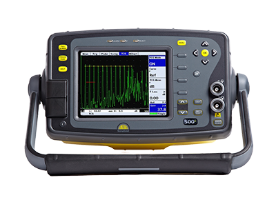
The Sitescan 500s offers the end user an entry level broad band flaw detector with full VGA display, sync and proportional outputs and a 50nS (Spike) 200V Pulser. High levels of near surface resolution, penetrating power and excellent signal to noise ratio are key functions in the Sitescan range. The 500S has a color transflective VGA display, providing high visibility in any lighting condition and the enhanced user interface and full A-Scan display is available at the touch of a button. The 500S enclosure is constructed using impact resistant materials and is designed to meet IP67 standards, offering excellent water resistance and harsh conditions. Typical applications are Weld Fabrication, Corrosion Detection, Forgings & Castings and general UT inspection.
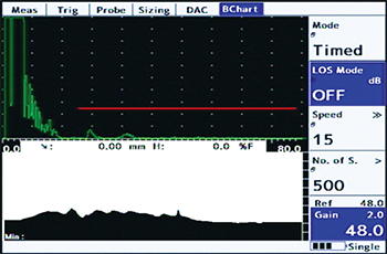
The Corrosion Software option includes the B-Scan display function which shows the cross section of the material based on its wall thickness. The B-Scan has selected update rates from 3 to 10 times per second, and can be stored with the thickness readings and transferred to the PC via UTLity.
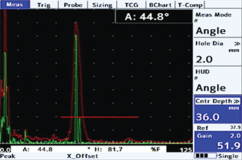
Quick accurate measurement of beam profile is made easy by the new angle measurement mode. The instrument automatically converts the indication from a side drilled hole of known diameter and depth to the angle of the reflector from the beam exit point. Using the built-in peak detection mode, as shown, the beam profile for any transducer can be confirmed in moments.
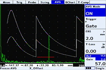
AVG/DGS software can be configured for any transducer and gives repeatable sizing of flaws with direct readout of Equivalent Reflector Size. The visible ERS curve can be adjusted to display the desired acceptance level and used to trigger the alarm and measurement reading.
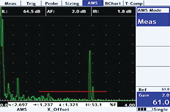
With this option enabled, measurements of Indication Level (IL), Attenuation Factor (AF), and Indication Rating (IR) are calculated and displayed in accordance with AWS D1.1.

UTLity software provides everything you need to manage your inspection data. The Standard version is FREE with every instrument and gives you the ability to view, move and manage Calibrations, A-Scans, B-Scans and Thickness Logs both on the instrument and on your PC. With UTLity you can also create customized inspection report templates, cut and paste information to other applications, and create printable pdf documents.
| Test Range: | 0.4" to 394" (1mm to 10,000mm) |
| Velocity: | 1,000 - 10,000 m/s continuously variable |
| Probe Zero: | 0 to 1,000 μs |
| Delay: | 400" (0 - 10,000m) in steel at 5930m/s (19455f/s) |
| Gain: | 0 to 110dB adjustable in 0.5, 1, 2, 6, 10, 14 and 20 dB steps |
| Test Modes: | Pulse Echo and transmit/receive |
| Pulser: | 200V fixed. 50nS square wave. Rise/Fall times <15nS into 50R load. |
| Damping: | 50 and 400 ohm damping selectable |
| P.R.F.: | Adjustable 5Hz to 1kHz. External sync also available. |
| Screen Update Rate: | 60Hz |
| Rectification: | RF, Fill wave, +ve half-wave and -ve half-wave. |
| Frequency Range: | 1.0MHz to 14Mhz (-3dB) |
| System Linearity: | Vertical = 0.5% Full Screen Height (FSH). Horizontal = +/- 0.2% Trace Full Screen Width (FSW). |
| Reject (Selectable): | Up to 80% Linear reject (removes baseline noise without affecting indication amplitude) or Up to 50% Suppressive reject (increase zero offset and reduces amplitude of all echoes). LED Warning when active. |
| Units: | Imperial (in), Metric (mm) |
| Display: | Color Transflective VGA (640 x 480) TFT Display Area: 4.57" x 3.43" (116.16 x 87.2mm) A-Scan Area: 400 x 510 pixels (normal), 460 x 620 (FS) Colors: 9 color palette with variable brightness |
| Gate Monitor: | Two independent gates for measurement and monitoring. Start and width fully adjustable over the entire range of the instrument. Levels adjustable from 0% to 100%, positive or negative triggering on each gate with audible & visual alarms. Gate resolution is 5nS. |
| Zoom: | Expands range and delay to cover the area set by Gate 1 start & width controls. |
| AGC: | Automatic Gain Control automatically sets the signal in Gate 1 to a level between 10% and 90% FSH, tolerance between 5% and 20%. |
| Measurement Modes: | |
| Mode 1: | Signal Monitor, Gate Alarms can be active but no measurements are displayed. |
| Mode 2: | Depth and amplitude of first signal in gate. |
| Mode 3: | Echo-Echo distance measurements. |
| Mode 4: | Trigonometric display of beam-path, surface distance (including X-offset) and depth of indication from the inspection surface together with echo amplitude. Curved surface correction can be applied for convex and concave surfaces. Half-skip can be indicated on screen. |
| Mode 5: | Gate to Gate distance measurement |
| Mode 6: | Flank to Flank |
| Mode 7: | Beam Angle, calculated from beampath, hole radius and hole center depth |
| Measurement Display: | Live display and updates on screen at 10 times per second. Large display of a single measurement available. |
| Waveform Smoothing Select from: |
|
| Auto-Cal: | Provides automatic calculation of velocity and probe zero from 2 reference echoes. Automatic calibration with two echoes. |
| Reference Waveform: | Displays a previously stored A-log in a color different from the active display: enabling a quick visual check of the differences. |
| Clock: | Built-in battery backed RTC keeps time and date. Visible on the status line, always stored with Panels, A-logs, etc. |
| Internal Memory: | 4GB storage available for A-Scans, panels, T-logs, B-logs, etc. 450,000 Panels, 200,000 A-Logs, 300,000 B-Charts, 440,000 T-Logs. |
| Active Peak Memory: | Retains all A-Scans on screen for echo-dynamic pattern analysis, with the active A-Scan displayed in a separate color. |
| Notes: | Alphanumeric labelling for panel stores, A-logs, B-logs, etc. |
| Display Freeze: | Hold the current waveform on screen for off-line processing. |
| Help Key: | Shows software and hardware information. |
| Language Support: | Multiple languages are selectable from a list including: English, French, Spanish, Russian, Chinese (Modern). Others are available on request. |
| Encoder Connection: | D-Sub 15 Connector (500S) |
| Video Output: | Standard on 500S |
| Proportional Outputs: | Available on 500S |
| External Sync: | Available on 500S |
| USB Connection: | Internal storage shown as Memory Device. |
| Transducer Sockets: | BNC or Lemo (factory option) |
| Power: | Lithium Ion 14.4V battery pack. Typically 16 hrs. for Sitescan 500S. Indication of battery charge status. Recharge time 3-4 hrs. Battery can be charged separately. Mains pack optional. |
| Charger: | 100-240 VAC, 50-60 Hz |
| Environmental: | Case sealed to IP67 |
| Temperature: |
Operating: 14° to 131°F (-10° to 55°C) |
| Size: | 5.7" x 10" x 5.7" (145 x 255 x 145mm) (HxWxD) |
| Weight: | 5.5 lbs. (2.5 kg) with battery. |
| Warranty: | 2 year |
| Extended Warranty: | Sonacover - extended 5 year warranty, including 4 calibrations |
| Calibration Standard: | EN12668-1:2020 (Detailed Specification available upon request) |
| Standards: | Vibration to 514.5-5 Proc 1 Annex C Fig 6 Shock 516.5 Proc 1 15g/6ms Explosive atmospheres - MIL-STD 810G Methos 511.5, Procedure 1 |
| Sizing Technique | Description | Standard or Optional |
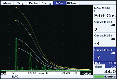
| DAC | Defined by up to 20 reference points or converted from TCG curve and digitally drawn on the screen. DAC curves meet the requirements of EN, ASME, JIS and many other standards. Custom DAC curves can be selected. DAC dynamic range can be extended by automatically adjusting the reference curve to match the reference gain. Scanning Gain and T- Loss available as separate controls. Amplitude readout is selectable between %FSH, % DAC or relative dB. | Standard |
| TCG | Time corrected or “Swept” gain, defined by up to 10 reference points or converted from a DAC curve. All points converted to 80% screen height. | Option |
| Backwall Echo Attenuation (BEA) | 0-40dB attenuation applied to the latter part of the time base, to improve the detectabilityof defects near the back wall and the loss of BWE due to porosity. | Option (requires TCG) |
| AWS | Built-in calculation and display of factors and parameters required by AWS D1.1. | Option |
| AVG/DGS | Enables the calculation of pseudo “DAC” curve and equivalent reflector size of UT indications, based on user input of transducer parameters. | Option |
| API | On-board flaw sizing method in accordance with API 5UE. | Option |
| Interface Trigger | Unlocks the interface trigger gate controls, which hold off the A-Scan acquisition and display until an interface echo is detected within a specific range and amplitude. Used for the elimination of water-path. | Option |
| Corrosion/B-Scan Software Option | Enables complex inspection plans to be uploaded from a PC using the on board Utility software. Features include 2 dimensional thickness logging, storing A-Logs and B-Logs with thickness values, taking multiple readings per location and note creation for each grid location. B-Scan option available to display bar-graph views of thickness readings taken by Gate 1 against distance or time. | Option |
| Split DAC & DGS/AVG | Adds up to 3 zones of added gain (+12db, +24dB) to the DAC or DGS/AVG curve to enable single-pass scanning of large sections and attenuative materials. Conforms to EN583-2:2001. | Option |
| Description | Part # | Saved | Price | Select Option | Add to |
|---|---|---|---|---|---|
| Sonatest Sitescan 500S Portable Flaw Detector | UT-ST-500S |
|
Request Pricing | ||