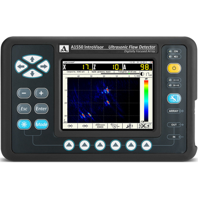
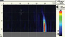
The IntroVisor is an Ultrasonic Flaw Detector and Tomograph with an antenna array probe digitally focused to all points of the material cross-section.
The A1550 is light and easy-to-use. It is designed to handle most ultrasonic flaw detection tasks quickly and easily.
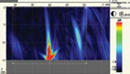
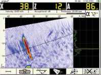
The internal structure of the test object is represented in real-time as a cross-section image that makes interpretation much easier compared to a traditional detector. Flaw images are sharper and better focused than UTPA instruments.
Speed and Efficiency
Efficient, high performance flaw locations in welds, castings and forgings as well as composites with documented test details.
The internal structure of the test piece represented in real-time as cross-section images with 25 frames per second update time.
Possibility to perform ultrasonic flaw detection along the welding joint without time consuming zig-zag scanning, due to the big aperature of the digitally focused array and scanning with virtual focus on long distances, which considerably reduces time for preparing the near-welding surface, increasing testing productivity.
High frame update rate on the screen allows scanning speeds up to 2 inches (50 mm/s).
Testing Reliability
The A1550 IntroVisor works based on the basis of a digitally focused array method (DFA), reconstructing tomographic images focused in every point of the interrogated materials cross-section, ensuring the best spatial resolution and maximum sensitivity to the entire cross-section of the material.
High test productivity
Sensitivity to all common flaws.
Better detectability of vertically-oriented flaws that are often missed of undersized by other techniques.
Visualization Modes:
The A1550 Tomograph offers 5 modes of discontinuity visualization. The modes is selected depending on the purpose of inspection and the nature of the test piece. Modes are marked with special symbols as shown below. Here is a general description of them:
Test Object: half-space
Testing Object: slab, T=0.4"-4"(10-100mm)
Testing Object: plate, T=>0.4" (10mm)
Testing Object: slab or plate, t=<4" (100mm)
Testing Object: slab or plate, T=<4" (100mm)
Reflector: point
Sounding: direct
Purpose: For objects of irregular shape, without definite thickness or objects with rough back surface.
Reflector: point
Sounding: direct and reflected
Purpose: For plane parallel objects with known thickness.
Reflector: point
Sounding: reflected
Purpose: For plane parallel objects with known thickness, small thickness objects while finding flaws near the surface.
Reflector: flat
Sounding: direct and reflected
Purpose: For detection of vertically-oriented flaws and plain surfaces, mirroring the ultrasound.
Reflector: volumetric
Sounding: direct and reflected
Purpose: Universal mode for plane-parallel objects with known thickness and all types of discontinuity flaws.
Extra Features:
The A-Scan function in Tomograph mode is provided to visualize the A-Scan impulse signal, plotted by a controlled line of the cross-section. It also evaluates the flaw depth and angle of probe, ensuring correct and quick choice of a single transducer when switching to the Flaw Detector mode.
Measuring signal level and coordinates of reflectors in every point of the tomogram display.
Setting the scale and position of the visualization area in relation to the DFA Antenna Probe.
Two fully adjustable 2D gates for automatic measuring of the flaw coordinates.
On-line control of image contrast.
Choice of a color template.
Creating, saving and choosing settings for a specific object.
Saving a viewing tomograms and echo-signals from memory.
Semiautomatic sensitivity calibration by standard samples.
2D system of spatial sensitivity adjustment to find and evaluate small flaws according to common codes and size flaws and position correctly at the whole surface of the test piece.
Inspection in the three-level reflector estimation system: «examination-reporting-acceptance» with color gradation of the tomogram image levels and automatic comparison to the reference level.
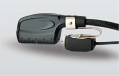
Scanning along welding line with an antenna array equipped with an encoder (optional) makes it possible to get a reliable graphic view of the test piece cross-section in a form of C-and D-Scans.
Software:
With our special software A1550-IntroVisor, you can send data saved on the device to an external PC so that results of an inspection can be processed, documented as tomogram images and A-Scan echo signals with parameters of the inspection and archived afterwards.
Operation Modes
The A1550 IntroVisor has three basic operation modes and a function of setting a configuration for every particular object to be promptly selected later:
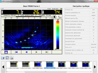
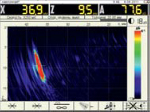
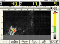
Tomograph Mode
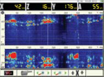
Works with DFA Antenna Arrays and real-time construction of tomograms. At this mode, not only tomograms (B-Scan) are displayed but all service information as well including gates, cursors, digital indicators, etc...
When a flaw is located, it is evaluated and estimated by the following methods: classical (comparing the reference reflectors signal amplitude) and by direct point measuring proximately by the flaw image.
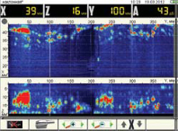
Scan Mode
Provides work with the DFA and the encoder while scanning along a welding joint.
C- and D- tomograms are displayed in real-time.
When a flaw is located it real size can be evaluated with a cursor moving in three coordinates (distance, length, depth). It makes it much easier to get information about the location and conventional length of the detected flaw.
B-tomograms can be displayed by moving the vertically oriented cursor along the reconstructed image for a graphic view of the inner structure of the testing object.
Flaw Detector Mode
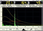
In this mode, the A1550 IntroVisor operates as a tradition ultrasonic flaw detector with classic normal or angle transducers. Signals are displayed as A-Scans.
The A1550 IntroVisor has all the features of a modern flaw detector (built-in DGS-diagrams, TCG and DAC, multilevel digital monitor, programmable form of the emission pulse, etc...) This mode provides correct evaluation of detected flaws according to standard code requirements.
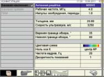
Setup Mode
Setup Mode is used to set and select parameters and working configurations.
It is possible to create a number of working configurations for various objects of inspection saving them under unique names. The required configuration is selected from the list right at the object.
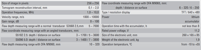
Specifications:
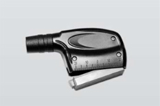
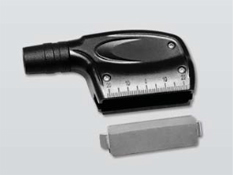
Types of Digitally Focused Arrays
For various fields of application the A1550 tomograph uses the following arrays:
M9060 4.0V0R0X10CL - 16 elements longitudinal wave array with central operation frequency of 4 MHz and scan zone of ±50°. It is used to test material and plastic objects.
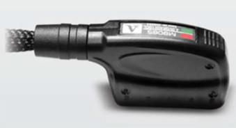
M9065 V.0V60R40X10CS - 16 elements shear wave array with central operation frequency of 4 MHz and scan zone from 35° to 80°. It is used to test welding joints including austenitic stainless steel. This array is distinguished by the absence of a large refracting prism.
Thanks to the DFAs construction the acoustic modules can be replaced as they wear out. The user can replace a worn-out acoustic module by hand and without tools or extra operations. This way ultrasonic testing can be conducted practically non-stop, increasing productivity.
The replaceable acoustic modules can be fitted to various diameters of pipes, expanding the range of tasks to be solved with the ultrasonic testing.
Features of DFA:
Various types of waves can be used:
Shear waves for testing welding joints with a scan sector covering the whole range of ultrasonic entry angles required by codes.
Longitudinal waves for testing the main body of metal.
The acoustic module of the DFA can be replaced by hand.
Quick switching between different types of DFA.
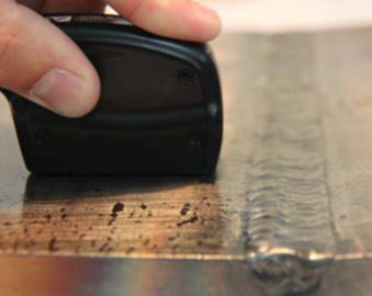
DFA Antenna Array Probes can be moved along the welding joint line without cross scanning thanks due to large aperature and long distance scanning with a virtual focus. It takes less time to prepare the near-welding surface of welding joints increasing the efficiency.
DFA can be used with an encoder (supplied optionally).
A1550 IntroVisor Includes:
A1550 IntroVisor - Ultrasonic Flaw Detector - Tomograph Electronic Unit