


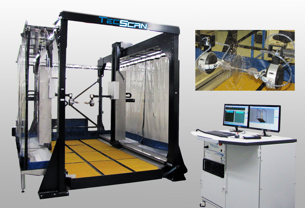
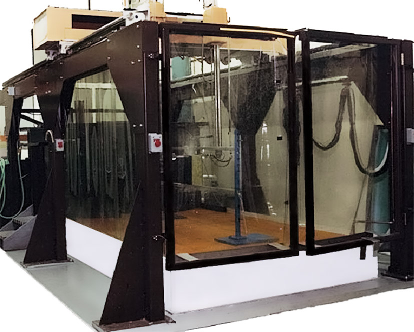
TecScan's Gantry System is an NDT industrial Squirter Gantry scanner designed for nondestructive quality testing and scanning of large structures and parts. The Gantry System is composed of an industrial mechanical scanner and a control room. The mechanical scanner is a large industrial Cartesian coordinate robot, which can accommodate up to 12 independent axes. The structure is made of structural steel components (Steel tube, I-Beams, Steel Plate, etc) welded together to increase rigidity.
There are 2 standard configurations to choose from:
Both configurations can be further customized to suit your needs.
With Single or Double Bridge
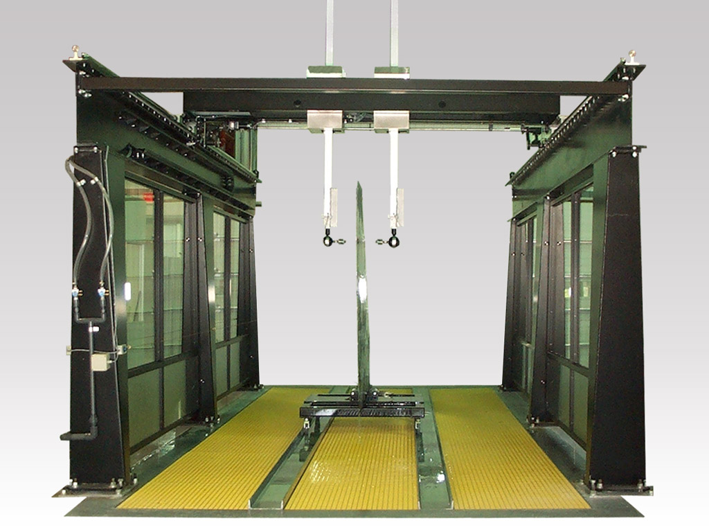
This configuration represents a 9-axis system with a single/double X-Axis bridge, two Y-Axes, two Z-Axes and two swivel/gimbal assembles. This gantry system is best suited for larger parts with less complex geometries. Inspection can be conducted in through-transmission and pulse-echo from each side simultaneously. This gantry system can be custom designed to meet clients’ needs.
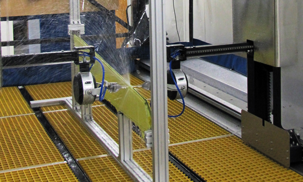
The Side-Arms Ultrasonic Gantry configuration is specially designed to perform 3D scanning of complex composite and metallic structures. Such Gantry System consists of 2 independent X-axis towers (X1 & X2), 2 horizontal Y carriages (Y1 & Y2), 2 Z-axis (Z1 & Z2), and two Swivel / Gimbal assemblies.
Both configurations use high quality servomotors equipped with gearboxes and optical encoders. The Gantry system also comes with all the required water metering and filtering equipment. Our Squirter Gantry Systems can be used in ultrasonic thru-transmission (TT) and Pulse-Echo (PE) testing techniques which are most commonly used when inspecting thick composite materials for delaminations; and sandwiched honeycombs for evaluating the presence of bond failure or crushed cores. The system produces A-Scan, C-Scan and B-Scan images of the inspected structure and defects as small as 1 mm can be detected and mapped on the 3D C-Scans.
Finally, the control room represents the center of operation of the Gantry system. It consists of an air-conditioned room equipped with industrial enclosures containing the workstation unit, all the required electronics including all motor drive electronics, as well as motion control and inspection hardware. The Gantry scanning system is operated using our TecView™ UT software package, which controls all the axes, sets up all inspection parameters and performs all required analysis of the collected data.
| Typical Scanner Specifications | ||||
| Axis | Max. Speed | Accuracy | Resolution | Repeatability |
| X | 36″/Sec | ±0.005″/’ | 0.0005″/Step | 0.01 mm |
| Y | 24″/Sec | ±0.005″/’ | 0.0005″/Step | 0.01 mm |
| Z | 12″/Sec | ±0.005″/’ | 0.0005″/Step | 0.01 mm |
| Gimbal A | 30°/sec | +/- 0.4° | 0.0005° | +/- 0.05° |
| Gimbal B | 30°/sec | +/- 0.4° | 0.0005° | +/- 0.05° |